|
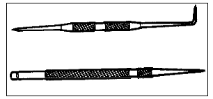
Scriber To obtain an accurate layout, fine lines must be scribed in the metal. A scriber (Figure 1-3) is the layout tool that is used to produce these lines. The point is made of hardened steel and is kept chain by honing on an oilstone.  Figure 1-3. Scribers.
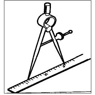
Divider When laying out circles, arcs, and radii, it is best to use the divider (Figure 1-4). The legs of the divider must be of the same length and be kept sharp. The divider cart be used to lay out and measure distances (Figure 1-5). To set the divider to the correct length, place one point on an inch mark of a steel rule and open the divider until the other leg matches the correct measure-merit required (Figure 1-6).  Figure 1-4. Divider |
Figure 1-5. Using divider to lay-out equal maesurement.  Figure 1-6. Correct methods of setting divider |
|
Trammel When scribing circles, arcs, and radii that are too large to be produced with the divider, a trammel should be used (Figure1-7). The trammel is made of three main parts: the beam, two sliding heads with scriber points, and an adjusting screw that is attached to one of the heads. The trammel can be made to scribe larger distances with the use of extension rods. This layout tool is set in the same manner as the divider.
Figure 1-7 .Trammel. Hermaphrodite Calliper The hermaphrodite calliper (Figure 1-8) is a tool used to layout lines that are parallel with the edges of the work piece(Figure 1-9). It can also be used to locate the center of cylindrical shaped workplaces (Figure 1-10).  Figure 1-8. Hermaphrodite calipers.  Figure 1-9 Laying-out lines parallel to the edge of workpiece. |
 Figure 1-10. Obtaining center of a cylindrical work. Surface Gage A surface gage (Figure 1-11) is used for many purposes, butis most often used for layout work. The gage can be used to scribe layout lines at any given distance parallel to the work surface (Figure 1-12).
Figure 1-11. Surface gage. |
|
Figure 1-12. parallel line scribed with surface gage. The spindle may be adjusted to any position with respect to the base and tightened in place with the spindle nut (Figure 111) The rocker adjusting screw provides for finer adjustment of the spindle by pivoting the spindle rocker bracket. The scriber can be positioned at any height and in any desired direction on the spindle by adjusting the scriber. A surface plate and combination square (Figure l-13) are needed to set the surface gage to the correct dimension. |
Surface Plate A surface plate (Figure l-14) provides a true, smooth, plane surface. It is used in conjunction with surface and height gages as a level base on which the gages and the work piece are placed to obtain accurate measurements. These plates are made of semi-steel or granite and should never be used for any job that would scratch or nick the surface.
Figure-1-14. A granite surface plate. |

 Figure 1-13 Setting surface gage scriber on plate 2.
|
Vernier Height Gage The vernier height gage (Figure 1-15) is a calliper with a special foot block to adapt it for use on a surface plate. Height gages are available in several sizes: the most common are the10, 18, and 24 inch gages in English measure and the 25 and46 cm gages in metric measure. Like the vernier calliper, these height gages are graduated in divisions of 0.025 inch and avernier scale of 25 units for reading measurements to thousandths of an inch. Always be sure the bottom of the foot block (Figure 1-15) is clean and free from burrs.
Figure 1-15. Vernier Height gage.
Figure 1-16 shows the height gage with a tungsten carbide marker. This marker is used to lay out lines on glass, hardened steel. or other hard materials. |
 Figure 1-16. Using height gage with carbide. Figure 1-17 illustrates the use of an offset scriber with the height gage. This scriber reaches below the gage base. Do not attempt to adjust the sliding jaw while it is clamped to the upright beam.
Figure 1-17. Using height gage with offset scriber. |
|
Combination Square Set The combination square set (Figure 1-18) is used for a number of layout operations. The set consists of a blade(graduated rule), square head, protractor, and center head. Blade The blade is designed to allow the different heads to slide along the blade and be clamped at any desired location. The groove in the blade is concave to eliminate dirt build up and permit a free and easy slide for the heads. By removing all the heads, the blade may be used alone as a rule. Square Head The square head is designed with a 45° and 90° edge, which makes it possible to be used as a try square and miter square. By extending the blade below the square, it can be used as a depth rule. The square head can also be used as a level. Protractor Head The protractor head is equipped with a revolving turret graduated in degrees from 0 to 180 or to 90 in either direction. It is used to measure or lay out angles to an accuracy of 1°. Center Head The center head, when inserted on the blade, is used to locate and lay out the center of cylindrical workplaces.  
Figure 1-18. Combination square set. Bevel Protractor The bevel protractor (Figure 1-19) consists of an adjustable blade with a graduated dial. The blade is usually 12 inches long and 1/16 inch thick. The dial is graduated in degrees through a complete circle of 360°. The most common use for this tool is laying out precision angles. The vernier scale is used for accurate angle adjustments and is accurate to 5minutes or 1/12°. |
 
Figure 1-19. Bevel protractor. STEPS IN MAKING A LAYOUT Planning before beginning any layout is one of the most important steps. Each job may require different layout tools depending on the accuracy needed; however, there are certain procedures which should be followed in any layout. Figure 120 shows a typical layout.
The layout tools mentioned in this section are only the most commonly used. For more information on the use and care of these tools and other layout and measuring tools, refer to TM 9-423. |
JIGS AND FIXTURES
The primary purpose of jigs and fixtures is to align the tool and hold the work piece properly during machining. A fixture is a device which holds the work while cutting tools are in operation. It differs from a jig in that it has no guides or special arrangements for guiding tools. A jig is also a fixture for locating or holding the work and guiding the cutting tool in operations such as drilling, reaming, counter boring, and countersinking.

.jpg) Figure 1-20. Typical layout.
Figure 1-20. Typical layout.
|
Jigs and fixtures can greatly reduce the cost of manufacturing large quantities of parts. Their use is also an advantage when the interchange ability and accuracy of the finished products are important. They also can be used in low or limited production jobs if extreme accuracy must be maintained. One of their greatest advantages is that relatively unskilled lab or can accomplish the job using these special tools. MECHANICAL DRAWINGS AND BLUEPRINTS Mechanical Drawings A mechanical drawing, made with special instruments and tools, gives a true representation of an object to be made, including its shape, size, description, material to be used, and method of manufacture. Blueprints A blueprint is an exact duplicate of a mechanical drawing. These are the most economical and satisfactory working drawings in use. They do not soil easily and are comparatively easy to read. Blueprint paper is a good grade of white paper coated with a chemical solution. making it greenish yellow. A blueprint is made by placing a tracing of a mechanical drawing on a sheet of blueprint paper and exposing it to light. During exposure. the light penetrates where there are no lines or printing on the tracing but does not penetrate where there are lines or printing. The print is then washed in water. which changes the exposed chemical to a dark blue and washes the chemical off where lines and printing prevented exposure. In other words. the process leaves white lines on dark blue background. Working From Drawngs Detail prints usually show only the individual part or piece that must be produced. They show two or more orthographic(straight-on) views of the object. and in special cases. they may show an isometric projection. without dimension lines, near the upper right corner. An isometric projection shows how the part will look when made. Each drawing or blueprint carries a number. located in the upper left-hand corner and in the title box in the lower right-hand corner of the print. The title box also shows the part name, the scale used, the pattern number. the material required. the assembly or subassembly print number to which the part belongs. the job order number, the quantity and date of the order. and the names or initials of the persons who drew. checked. and approved the drawings(Figure 1-20). Accurate and satisfactory fabrication of a part described on a drawing depends upon the following:
|
Limits of Accuracy Work must be performed within the limits of accuracy specified on the drawing. A clear understanding of tolerance and allowance will help you avoid making small, but potentially large errors. These terms may seem closely related but each has a very precise meaning and application. The paragraphs below point out the meanings of these terms and the importance of observing the distinctions between them. Tolerance Working to the absolute or exact basic dimension is impractical and unnecessary in most instances: therefore, the designer calculates. in addition to the basic dimensions, an allowable variation. The amount of variation. or limit of error permissible is indicated on the drawing as plus or minus (+ )a given amount. such as + 0.005 or + 1/64. The difference between the allowable minimum and the allowable maximum dimension is tolerance. When tolerances are not actually specified on a drawing, fairly concrete assumptions can be made concerning the accuracy expected. by using the following principles, For dimensions which end in a fraction of an inch. such as 1/8, 1/16, 1/32, 1/64. consider the expected accuracy to be to the nearest 1/64 inch. When the dimension is given in decimal form the following applies: If dimension is given as 2.000 inches, the accuracy expected is+0.005 inch: or if the dimension is given as 2.00 inches, the accuracy expected is +0,010 inch. The +0.005 is called in shop terms, "plus or minus five thousandths of an inch.” The + 0.010 is called “plus or minus ten thousandths of an inch.” |
|
|
Allowance Allowance is an intentional difference in dimensions of mating parts to provide the desired fit. A clearance allowance permits movement between mating parts when assembled. For example, when a hole with a 0.250-inch diameter is fitted with a shaft that has a 0.245-inch diameter, the clearance allowance is 0.005 inch. An interference allowance is the opposite of a clearance allowance. The difference in dimensions in this case provides a tight fit. Force is required when assembling parts which have an interference allowance. If a shaft with a 0.251inch diameter is fitted in the hole identified in the preceding example, the difference between the dimensions will give an interference allowance of 0.001 inch. As the shaft is larger than the hole, force is necessary to assemble the parts. |
Precautions Be sure you have the correct print for the part to be made or repaired. You want the print which has not only the correct title, but also the correct assembly number. Never take a measurement with a rule directly from the print because the tracing from which the print was made may not have been copied from the original drawing perfectly and may contain scaling errors. Also, paper stretches and shrinks with changes in atmospheric conditions. Dimensions must be taken only from the figures shown on the dimension lines. Be very careful in handling all blueprints and working drawings. When they are not in use, place them on a shelf, in a cabinet, or in a drawer. Return them to the blueprint file as soon as the job is done. Blueprints and working drawings are always valuable and often irreplaceable. Make it a point never to mutilate, destroy, or lose a blueprint. |


- Featured
- Best selling
- Alphabetically, A-Z
- Alphabetically, Z-A
- Price, low to high
- Price, high to low
- Date, old to new
- Date, new to old
No products found


